The game is a classic Japanese RPG (JRPG)-like adventure that combines exploration and battle. Like with most JRPG games, there are two modes of play: one that lets the player move around on a big world map, and another that facilitates the action (battles, puzzles, etc.).
In each mode, the game will present a tiled area, upon which the player character can move and so forth. In this post, I will focus solely on the big world map and how tiles can be made to fit together and present a professional-looking background.
The tiles will be laid out in an orthogonal fashion. That is, the tiles are shown at right angles to each other and the axes are perpendicular. In other words, it looks like this:
 |
| Figure 1: Orthogonal tile layout |
Tiles laid out in this fashion are made seamless when the opposing sides can be fitted together and give the appearance that there is no separation. This can be done with 3, 4, or even 6-sided tiles, but the most common approach is to use squares.
 |
| Figure 2: The seamless nature of game map tiles |
From the picture, you can see that there must be some kind of symmetry within the tiles. GIMP offers a few ways to achieve this effect, but if you understand how the edge symmetry works, it is possible to create seamless tiles with only a simple brush. Unfortunately, that kind of process also takes a lot of time to perfect, and I would much rather be writing code than spending a year on tweaking the hundreds of tiles I will eventually need.
So, to make a seamless tile, we need to begin with a square canvas. Open GIMP, and select File>New.... In the dialog, make sure the width and height are equal. The rest of the dialog options are not critical, but I like to add some descriptive text to the comments and set the background to Transparent.
 |
| Figure 3: Blank canvas for tile development |
With this file, we can create many tiles, each on a single layer or a group of layers. Let us now take a look at making a simple tile to represent rows of trees.
I already have a few leaf patterns on my system, so I will use one to quickly draw a top-down view of a tree in the center of the tile:
 |
| Figure 4: Tree drawn in center of tile |
Now, from the menu select Layer>Transform>Offset... and click on the Offset x/2,y/2 button. Make sure the Wrap Around option is selected. Press the Offset button on the bottom of the dialog, and you get something that looks like this:
 |
| Figure 5: Tree offset with tool |
In essence, the picture with the cluster of leaves in the middle is seamless because there are no pixels along the edges. However, this is an exercise in making something a seamless tile that may otherwise not be. In a later exercise, the use of the offset tool will become much more important. For now, let us complete this simple tile and see how it works to fill a large space in a seamless manner.
Add more leaves in the center so you get something like the following:
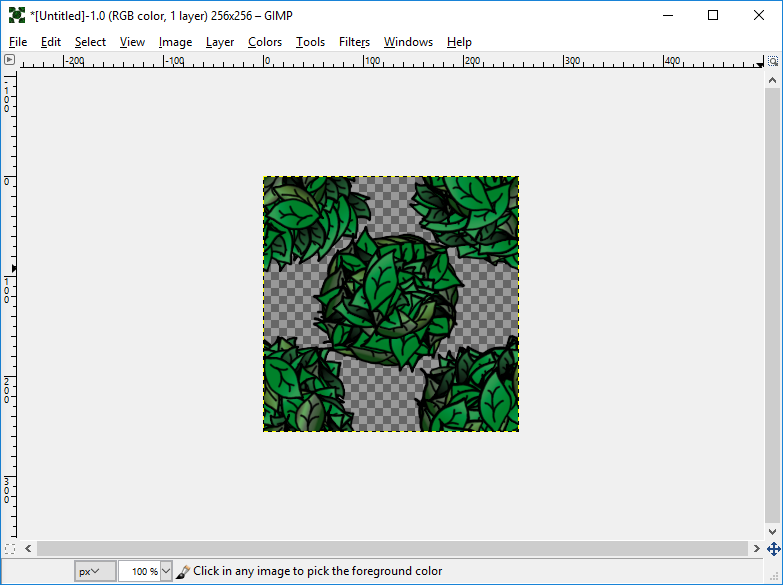 |
| Figure 6: Second tree added to center |
At this point, we have a tile composed of two tree images that will fit together very nicely.
One quick way to see how the tiling looks is to export the image as a pattern and then bucket fill a large space with the pattern.
You can create a pattern with this image by selecting File>Export As... and save the file as a GIMP Pattern (*.pat) to your Patterns directory. If you do not know where the Patterns directory is on your system, you can always look in the Folders category under Edit>Preferences. Once the pattern is saved, click on the refresh button on the Patterns dockable dialog and it will appear in the list:
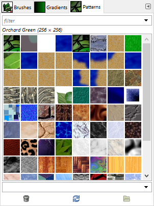 |
| Figure 7: Patterns with Orchard Green now added (Note the refresh button in the middle at the bottom of the dialog) |
I have given "Orchard Green" as the pattern description. You can see this in the picture above.
To quickly see how it looks, create a new GIMP file with a size somewhere three to ten times the size of the tile, and bucket fill the patten into the window. Here is a portion of an image showing the pattern I created:
 |
| Figure 8: Bucket-filled orchard pattern |
As it is, this particular tile is fine for a large background for something like a web page. However, it is not very useful on a game map, unless your map encompasses the entire screen. The problem with the tile is that the edges show only a part of a tree and as such will not make a map look very clean.
The utilization of the offset feature, however, shows how we can make something very useful on a map. That item will be a road.
Below, you will see the set of road tiles I have conceived for the game. Since they are only rough drawings, they are only used for reference. Note that there are six tiles which cover the six possible configurations for a section of a single road, without intersections.
 |
| Figure 9: Six possible road configurations |
The first one we will construct is the horizontal road tile.
In my game world, the main roads are similar to ancient Roman roads with large stones laid atop smaller ones. For the large stones I will use the Bricks pattern, and for the smaller ones I will use the Crack pattern. Both patterns come pre-packaged with GIMP.
For the actual drawing process, it is possible to select a brush, paint streaks of a custom brush with varying widths, opaqueness, and so forth, or we can simplify things a lot with the use of masks. Now, I will not go through the basics of masks, as that information can be found with a quick search through the net. However, I will describe a method of painting and modifying a mask in such a way that modifications for the six different road types will be simplified and easily modified for different types of environments.
To begin, we erase everything we did with the previous exercise and begin with a single transparent layer. On this, we bucket fill the entire space with black (HTML:000000). We then create a new layer group and rename it Masks. Now drag and drop the black filled layer into the Masks folder. All the masks we create will rest in this folder as normal, grayscale layers.
The concept of the horizontal road is shown below. The green border represents the tile boundaries, the brown streak in the middle will be the rocky road, the gray areas above and below will be the small rocks providing an easement, and the yellow background should be easily replaced with grass, dirt, or whatever generic landscape surrounds the road.
 |
| Figure 10: Road features |
We will use this concept to guide the actual construction of the road. We will also endeavor to create a mirror-like balance of the graphics so that we can rotate the image and have a vertical road tile, essentially creating two tiles out of one. Later, we will explore ways to make all the rest of the road tile types with just this one tile.
First, let's see what the brick pattern looks like in the space we have created for the new tile. A few guides have already been added to facilitate our process:
 |
| Figure 11: Tile with unmodified brick pattern |
A quick look at the pattern shows two rows of bricks that appear at approximately the center of the tile. Capturing the two middle rows of bricks to use as the large rock portion of the road makes sense, and so guide lines were laid down at 94 pixels and 162 pixels, allowing a reference for the approximate separation of the large rocks from the small rocks.
Although the pattern tiles smoothly with the bucket fill tool, the edges do not come together clean when we copy this tile and paste it into a larger picture, simulating the process of laying out the tiles in the game. There are a few ways to fix this, but the simplest one we have for a pattern like this can be found by selecting Filters>Map>Make Seamless.
Now, with the bucket-filled layer made seamless, when we copy and paste this version of the tile into a larger picture, we can see how the edges look much smoother. Here is a comparison of the edge artifact from the original tile and the improvements after running the seamless filter:
 |
| Figure 12: Untouched edges look a bit jagged (four tiles come together in the center) |
 |
| Figure 13: Edges look smooth after running Make Seamless filter |
The change is obvious and it will make the end result much more professional.
One more thing we will do is offset the layer a bit so that the two middle rows of bricks are as close to the center line as possible. Select Layer>Transform>Offset and set the X value to 0 and the Y value to 3. Alternatively, you may want a brick row in the center, so you would then set the Y value to something like 10 or -16. Experiment with this value and see which offset works best for you.
Now, to show the bricks only in the large rock portion of the road concept, we need to make a mask. Create a new transparent layer and label it Large Rock Mask. Then create a new layer group and call it Masks. Drag the Large Rock Mask layer into the Masks group. We will use this group as a repository for all the masks we create.
Select the Large Rock Mask layer and with the rectangle select tool, select the horizontal area bordered by the two guides we laid down and fill it with white. Then un-select everything.
Next, select the brush tool and one of the Splat brushes. Make sure the foreground color is white. Set the brush size to some value between 50 and 70, and select an appropriate brush dynamic. I often use the Pen Generic at this step. You may also want to check the Apply Jitter box.
Use this brush to paint along the top and bottom areas of the filled rectangle. The idea is to create a rough feathering effect as though bits of the large rock have crumbled at the edges to mix with the smaller rock farther out. Additionally, you may want to set the dynamics to Dynamics Random and choose the eraser to erode a bit of the edges. This bit of the procedure is purely dependent upon one's artistic style, but the concept road shown near the top of this post suggests frayed edges where the rocks meet.
 |
| Figure 13: Rough mask for large stone portion of road |
Once you have finished crafting the white portion of the mask, you need to make sure it is seamless. Because the only edges we must address are the ones east and west, we can offset the layer 128 pixels along the X axis (0 along the Y axis) and smooth out the portion in the middle.
When this is complete, you can add this as the mask to your large rock layer by selecting the entire frame (Ctrl-A) and copying it to the clipboard (Ctrl-C). Then, right-click on the large rock layer, select Add Layer Mask... from the popup window, select the Black (full transparency) option, and then click on the Add button.
At this point, the mask portion of the layer is active, so you can place your mask by pasting from the clipboard (Ctrl-V), right-click on the new floating layer, and select Anchor Layer from the popup window. This will anchor the white portion onto the mask and will now allow the layer to display only the middle portion of the bricks. If you haven't already done so, it would be a good time to rename the large rock layer to something meaningful like Large Rock.
 |
| Figure 14: Application of the mask to the large rock layer |
This method is generally the same for the small rock layer, except with a different pattern and another mask that reveals a wider portion. When placed under the large rock layer, you will get a rough, grayish easement around the road.
Before continuing, it would be a good idea to see how well this tile actually works. As it is a horizontal road, placing this tile horizontally next to itself will show how well we achieved the seamless attribute of the tile.
 |
| Figure 15: Road tile laid three wide |
As you can see, with a plain green background added, this tile lays down very seamlessly and it looks fantastic.
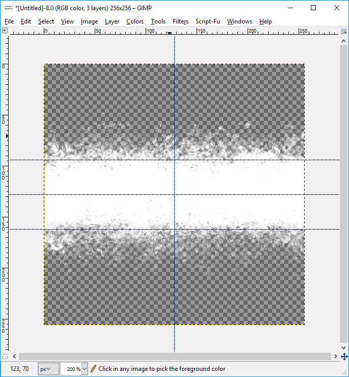
Below is a picture of the mask for the small rock area and what the small rock layer looks like with the application of the mask. Notice how the white pixels degrade above and below the grid lines specified for the large rock area. Also note the Crack pattern has been modified with the Make Seamless filter. The use of the Splats brush with alternating dynamics (usually Pen Generic and Dynamics Random) and the occasional application of the eraser create a randomized stippling effect that gives the illusion of eroded rocky areas.
 |
| Figure 16: Small rock mask |
 |
| Figure 17: Small rock layer |
Now, we test this look by laying the tiles again side by side with a green background. Once again the look is very clean and there are no visible seams.
 |
| Figure 18: Better road tiled three wide |
At this time you may want to experiment with backgrounds of dirt or grass. Because this tile and the game uses photo-like images, modified images of grass and dirt would look best here. One other good thing to do is create a new layer group and call it Horizontal Road. Then place the two rock layers in that group.
The vertical road is quickly made as all the layers can be rotated 90°. Just right-click on the Horizontal Road layer, duplicate it, and then select the new layer. It will be named Horizontal Road copy, but you should rename this to Vertical Road.
With Vertical Road selected, Choose Layer>Transform>Rotate 90° clockwise. You may also choose counter-clockwise, as either direction should give you a seamless vertical road tile.
 |
| Figure 19: Horizontal tile rotated to a vertical orientation |
Two of these tiles laid vertically show a perfect match at the seams:
 |
| Figure 20: Two vertical tiles making a northbound road |
This completes two of the six tiles needed for a road without intersections. The other four are bends in the road that take a 90° turn. We will label them W-N (as it connects the west side of the tile to the north side), W-S, E-N, and E-S. They are all created in a similar fashion, so this post will concentrate only on the W-N tile.
We want the seams on the edges to be the same as the horizontal and vertical tiles we just made. The main difference with the bends is how we merge the ends together with a smooth-looking path. To that end we divide the work into to phases: a) modifying the masks, and b) modifying the graphics.
Start with the large rock mask in its horizontal orientation. The west side of our W-N tile will need to match with tiles terminating on their eastern sides, so we must make sure the mask matches. In order to make the northern edge match tiles aligned on the north, we must add the vertical mask.
We begin the new mask with a new blank layer. Copy the horizontal mask into this new layer. Then, copy the vertical mask and paste it into the new layer as well. You will now have a layer we will eventually use for all the bend masks.
 |
| Figure 21: The base mask for all four bend tiles (large rock) |
For each bend, we merely start with this mask and erase the parts that do not belong, making sure we retain the same kind of eroded edge. For the W-N tile, we will keep the west and north parts of the mask and remove the east and south parts
Start by making a copy of this layer and work with the copy, naming it W-N Mask. Then, use the eraser tool with different brushes and dynamics to attain the same effect as with the other masks.
 |
| Figure 22: W-N large rock mask |
The bricks image needs to be modified as well, but we will need to do this in a different fashion. To make things simpler, the mask outlines a hard turn, and not a soft curve. This will let us carry the horizontal and vertical alignments of the bricks directly into the middle. We are going to need several layers for this, so we should create a new layer group called W-N. In this group, drop the new W-N mask.
Hopefully, you have saved the bricks graphic. If you did not, you can always duplicate the horizontal tile large rock layer and remove the mask. Copy this graphic and another rotated vertically into the W-N group. Create a layer mask for each one filled with black (full transparency).
Select the free select tool (Shift-F). and make a selection by clicking the top-left corner, the bottom-left corner, the bottom-right corner, and then again on the top-left corner. This will create a diagonal selection.
Now, make sure that the mask is selected for the horizontal bricks and fill the area with white. This will reveal the lower-left half of the graphic.
Invert the selection by choosing Select>Invert from the menu. Make sure the mask for the vertical bricks image is selected and fill the other area with white. This will reveal the upper-right half of the vertical bricks image.

 |
| Figure 23: the two layers properly masked out. |
These need to be combined into one layer. First, make sure both are visible, then right-click and select Apply Mask on the popup to both layers. Right-click on the upper layer and select Merge Down. This will create a layer we can now use with our mask.
Create a new mask (black full transparency) on this layer. Copy the W-N mask we made earlier with Ctrl-C. Make sure the mask on the combined brick layer is selected and paste the large rock mask in with Ctrl-V (be sure to anchor the pasted layer).
We now have something which is passable:
 |
| Figure 24: Mask applied to large bricks combined image |
The same technique is used with the small rock layer. When combined, they look like this:
 |
| Figure 25: W-N road curve with both rock layers |
We test the edges by laying a road tile on the west and north edges of this tile.
 |
| Figure 26: Three road tiles connected to form a bend |
This looks great. The bricks in the W-N tile could use a bit of tweaking, but the majority of the work is done.
From here, you can build an assortment of road tiles, depending upon your needs. The golden rule for road creation is to ensure the tiles show no obvious seams where they join.
There are other ways to accomplish the same thing, but I have found the layer offset feature and the Make Seamless filter to be invaluable in my graphics work.